Product Details:
Brand: MOOG
Model number: G122-824-002
Colour: new
Warranty: 12 months
Lead Time: 3-day working day
Country of origin: Germany
Price: Please contact us
Product weight: 0.235kg
Shipping Port: Xiamen, China
Payment:T/T
Express cooperation: fedex, DHL, UPS and your express account
Service: Professional Sales provides 24 hours /7 days online service
Product Dimensions:
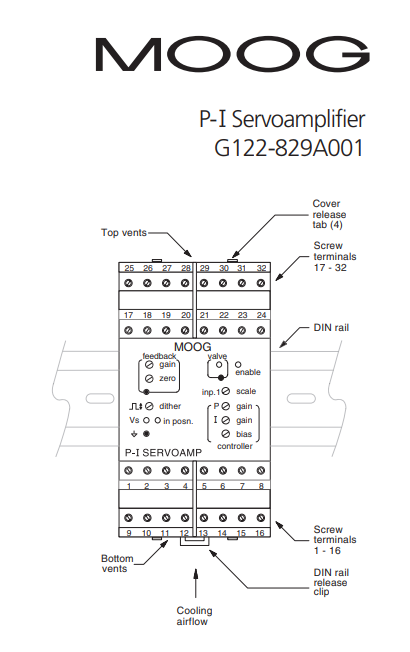
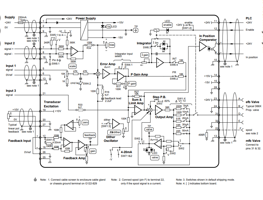
These Application Notes are a guide to applying the G122-829A001 P-I Servoamplifier. These Application Notes can be used to: Determine the closed loop structure for your application. Select the G122-829A001 for your application. Refer also to data sheet G122-829. Use these Application Notes to determine your system configuration. Draw your wiring diagram. Install and commission your system. Aspects, such as hydraulic design, actuator selection, feedback transducer selection, performance estimation, etc. are not covered by these Application Notes. The G122-202 Application Notes (part no C31015) cover some of these aspects. Moog Application Engineers can provide more detailed assistance, if required.

The use of crimp “boot lace ferrules” is recommended for the screw terminals. Allow sufficient cable length so the circuit card can be withdrawn from its case with the wires still connected. This enables switch changes on the circuit card to be made while the card is still connected and operating. An extra 100mm, for cables going outside the enclosure, as well as wires connecting to adjacent DIN rail units, is adequate. The screw terminals will accommodate wire sizes from 0.2mm2 to 2.5mm2 (24AWG to 12AWG). One Amp rated, 0.2mm2 should be adequate for all applications.

The circuit card needs to be withdrawn from its case to set the selector switches, change the plug-in resistors and operate the step push button. To do this, push one cover release tab with a pen or screwdriver, while gently pulling on the top cover on that side. The cover will release approximately one mm. Repeat on the second tab on that side. Repeat on the other side and then withdraw the cover and circuit card until the required switches are exposed. The rigidity of the connecting wires will hold the circuit card in position while changes are made.
Our service:

Fast delivery, and can be used with your express account.

Competitive Price

Free Shipping

One-year warranty